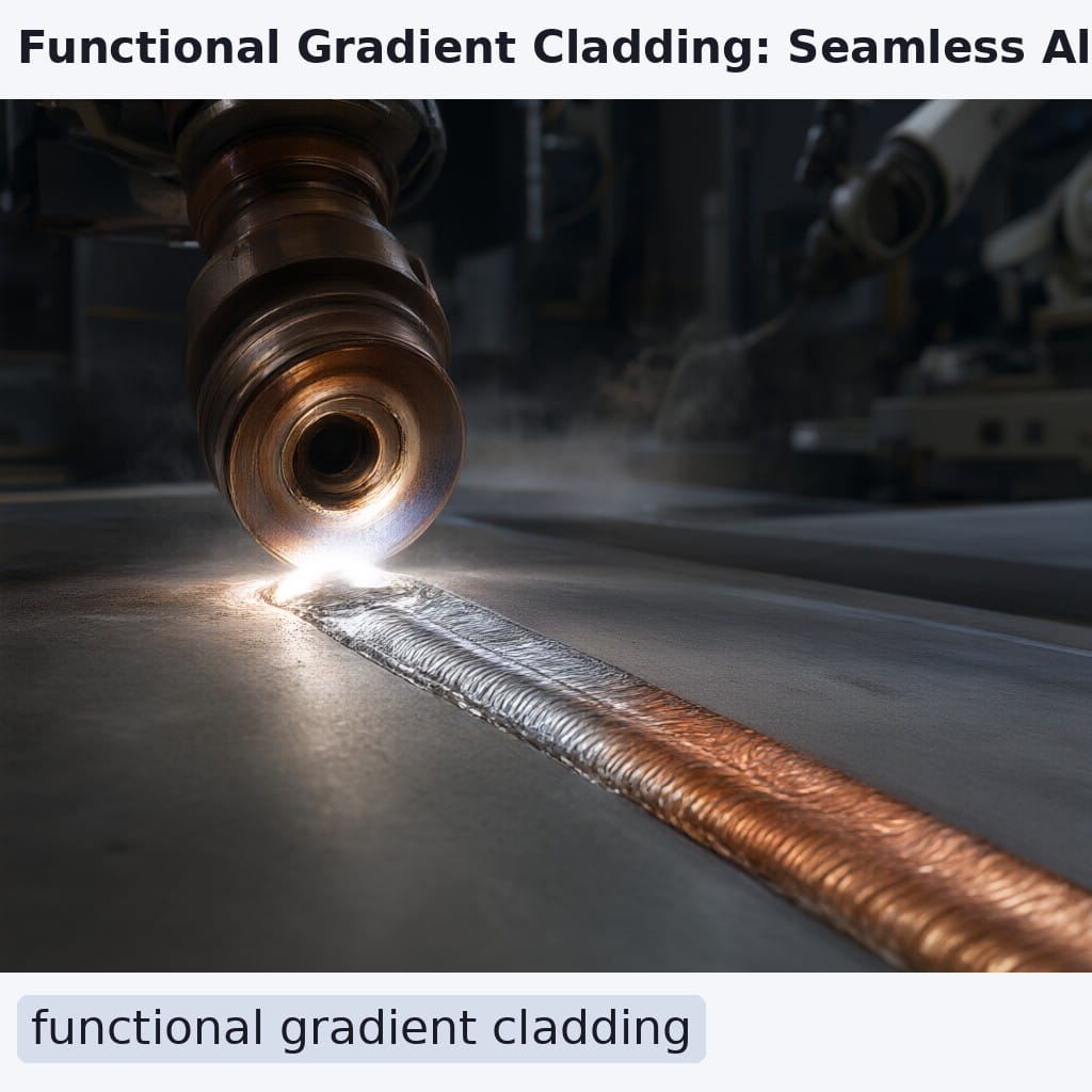
Functional gradient cladding solves a fundamental engineering paradox: how to give one component two contradictory material properties without creating a weak boundary. Instead of bonding separate layers—each prone to delamination, corrosion, or stress concentration—it builds a single, continuous structure where composition shifts gradually from core to surface. This eliminates sharp metallurgical transitions that often become failure initiation sites in demanding applications like turbine blades, mining tools, or chemical pump shafts.\n\n## How Real-Time Powder Blending Enables True Gradients\n\nTraditional laser metal deposition lays down one alloy per pass. Functional gradient cladding? It’s more like conducting an orchestra of powders. At Intouch, our laser cladding equipment uses dual-hopper powder feeders feeding into a coaxial nozzle, each independently metered with millisecond-level control. As the laser melts the substrate, the system continuously adjusts the blend ratio—say, from 100% Inconel 718 at the base to 100% Stellite 6 at the top—over a programmed deposit thickness.\n\nThis isn’t just mixing; it’s precision choreography. The controller updates the powder ratio every 100 milliseconds based on real-time mass flow feedback, ensuring the gradient follows the exact profile you define—whether by layer count or cumulative height. For a standard 2 mm thick deposit transitioning between nickel- and cobalt-based alloys, the system typically executes 10 discrete compositional steps. Post-process verification via EDS line scans confirms ±2 wt% accuracy at each checkpoint, per internal process validation protocols aligned with ISO 9001:2015 standards.\n\nWhy does this matter on the shop floor? Because abrupt changes in chemistry create internal stresses. A smooth transition? That’s resilience built in—literally.\n\n![Inline: Close-up of coaxial laser cladding nozzle with dual powder streams converging into molten pool during functional gradient deposition. Photorealistic industrial setting, no logos.]\n\n## Solving Real-World Extremes with One Continuous Process\n\nThe power of gradient cladding shines when components must survive opposing demands. Consider these three high-stakes scenarios:\n\nThermal Barrier Coatings (TBCs) That Don’t Spall
Conventional TBCs stack a metallic bond coat (like MCrAlY) directly onto a ceramic topcoat (YSZ). Their mismatched coefficients of thermal expansion (CTE) cause cracking after just a few hundred cycles. With functional grading, the interface isn’t a cliff—it’s a ramp. Over a 200 μm transition zone, composition shifts gradually, accommodating CTE differences. industry data shows this approach can extend thermal cycling life from ~500 to over 1,000 cycles—effectively doubling service intervals in gas turbines or exhaust manifolds.\n\nForging Dies That Outlast Homogeneous Clads
Hot forging dies need toughness deep inside to absorb impact, yet extreme surface hardness to resist galling and wear. A gradient from H13 tool steel (core-compatible) to Vanadis 4 Extra (surface-hard) delivers both in one pass. Field trials report up to 3× longer die life compared to parts clad entirely with Stellite 6—a homogeneous solution that sacrifices toughness for wear resistance.\n\nPump Shafts Resisting Both Corrosion and Abrasion
In chemical processing, a single shaft may face acidic corrosion at the impeller end and mechanical wear at the bearing journal. Instead of welding two different sleeves together—a joint vulnerable to galvanic attack—gradient cladding deposits Hastelloy C-276 near the wetted end and smoothly transitions to Inconel 625 toward the dry, load-bearing zone. No weld. No crevice. Just one monolithic part built for dual threats.\n\nThese aren’t theoretical edge cases. They’re daily challenges for operators of laser hardfacing and powder feed cladding systems across oil & gas, power generation, and heavy machinery sectors.\n\n## Why Eliminating Joints Pays Off—Fast\n\nThink about every bimetallic component you’ve seen: shrink-fitted rings, welded overlays, bolted inserts. Each joint is a liability. It’s a potential leak path in pressure vessels. A stress riser under cyclic loading. A galvanic cell when dissimilar metals contact in electrolytes.\n\nFunctional gradient cladding erases those compromises. By fusing property gradients directly onto the substrate—no intermediate joining step—you get a truly monolithic part. And that simplicity translates straight to your bottom line.\n\nTake a large chemical reactor shaft: 200 mm diameter, 3 meters long. Traditionally, you’d weld a Hastelloy sleeve onto a 316L stainless base, then perform post-weld heat treatment (PWHT) to relieve stresses. With gradient cladding? You skip the weld entirely. Manufacturer data indicates this cuts total fabrication cost by up to 40% while removing the PWHT cycle—saving days of downtime and kilowatt-hours of energy.\n\nEven better: because there’s no heat-affected zone from a fusion weld, distortion is minimized. Final machining allowances shrink. Scrap rates drop. And since the gradient is deposited in situ, you avoid inventory costs for pre-fabricated bimetal blanks.\n\n| Approach | Joining Required? | PWHT Needed? | Estimated Cost Reduction | Service Life Gain |\n|——–|——————|————–|————————–|——————-|\n| Conventional Bimetal (Welded) | Yes | Yes | — | Baseline |\n| Functional Gradient Cladding | No | No | Up to 40% | 2–3× longer |\n\nThis ROI isn’t speculative. It’s baked into the process physics—and validated across thousands of hours of industrial use on laser cladding machines like Intouch’s IT-RF5018 series.\n\n## FAQ\n\n### How do you confirm the gradient matches the target composition?\n\nAfter deposition, we cut cross-sections and run Energy Dispersive X-ray Spectroscopy (EDS) line scans perpendicular to the clad-substrate interface. Scans are spaced every 50 μm through the deposit thickness. Per Intouch’s internal qualification protocol—which aligns with ISO/IEC 17025 principles—we perform five independent line scans per test coupon. Acceptance requires measured composition to stay within ±3 wt% of the programmed target at each designated transition point.\n\n### Can you apply gradient cladding to in-service or repaired parts?\n\nAbsolutely—provided the substrate material is compatible with the first alloy in your gradient sequence (the one touching the base metal). Before starting, we use handheld XRF (X-ray fluorescence) to verify the actual substrate chemistry. This “bond check” ensures metallurgical compatibility and prevents unexpected intermetallic formation. Most carbon steels, stainless grades, and nickel alloys accept gradient overlays with proper preheat and parameter tuning.\n\n### What laser power range is needed for effective gradient cladding?\n\nEffective deposition typically starts at 3 kW and scales up to 12 kW, depending on part size, desired track width, and powder feed rate. Intouch’s laser metal deposition systems—such as the IT-RF5018-1 flatbed or IT-RF5018-2 robotic variants—use fiber lasers with 600 μm core delivery (QBH interface) to balance penetration depth and melt pool stability. Lower powers (3–6 kW) suit thin-wall or precision applications; higher powers (8–12 kW) enable faster buildup on large components like rolls or shafts.\n\n### Is gradient cladding limited to two materials?\n\nNot at all. While most industrial applications use a binary transition (e.g., Alloy A → Alloy B), the control architecture supports multi-material sequences. You could program A→B→C if your component needs three distinct property zones—say, corrosion resistance → toughness → wear resistance along a single axis. The limiting factor isn’t the software; it’s powder handling logistics and metallurgical compatibility between adjacent blends.\n\n## Related Reading\n\n- Cryogenic Cladding: Strengthening Steel at Absolute Zero – Explore how low-temperature deposition refines microstructure for ultra-high-strength overlays.\n- Thermal Barrier Cladding: Surviving the Inferno – Dive deeper into YSZ and MCrAlY systems for extreme-heat applications.\n\nFor over two decades, Guangdong Intouch Technology has engineered laser cladding systems that turn material science into manufacturing advantage. Whether you’re rebuilding worn shafts or designing next-gen turbine components, our IT-RF5018 platform delivers the precision, power, and process control needed for true functional gradients. Reach out at info@intouchray.com or visit www.intouchray.com to discuss your application.”,
“image_prompts”: [
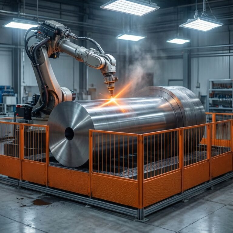
“Photorealistic industrial scene showing functional gradient cladding in action: a coaxial laser nozzle depositing a dual-powder stream onto a rotating shaft, with visible compositional transition from dark (corrosion-resistant alloy) to light (wear-resistant alloy) along the clad height. Brand-neutral, no logos, workshop lighting.”,
“Close-up of coaxial laser cladding nozzle with dual powder streams converging into molten pool during functional gradient deposition. Photorealistic industrial setting, no logos.