Key Considerations in Automated Seam Tracking
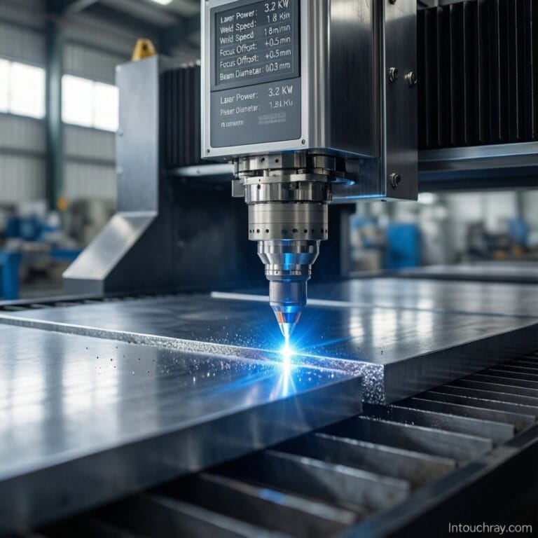
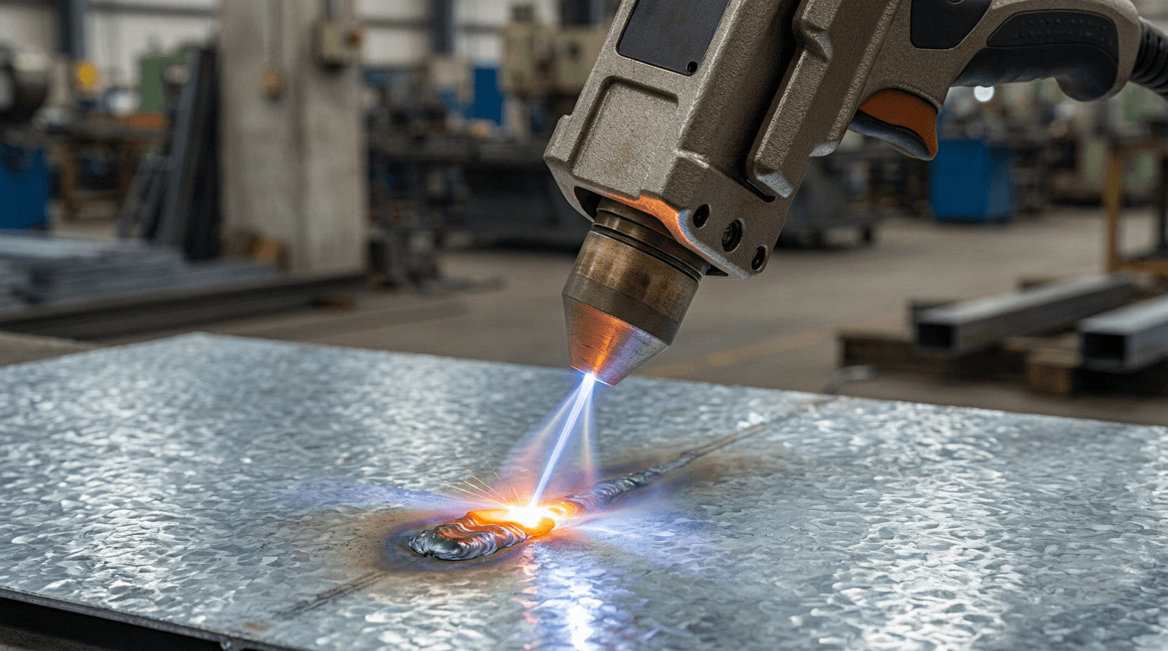
Automated seam tracking is the difference between a weld that follows the joint and one that wanders. In robotic laser welding — where travel speeds reach 1.8 m/min on 1mm stainless and positioning accuracy must stay within ±0.03mm — the human eye cannot react fast enough to correct drift. Seam tracking sensors close this loop by detecting the joint position in real time and adjusting the robot path before the laser fires.
The three dominant sensor technologies are laser profilometry (structured light), through-arc sensing, and vision-based tracking. Laser profilometry projects a laser line across the joint and uses a camera to measure the profile — it detects gap, mismatch, and seam position simultaneously, operating at 50–200 Hz. Through-arc sensing monitors voltage/current fluctuations as the electrode oscillates across the joint — effective for TIG and MIG but not applicable to autogenous fiber laser welding which has no electrode. Vision-based systems use CMOS cameras with bandpass filters tuned to the welding wavelength, capturing the molten pool and seam position in a single frame.

Seam Tracking Sensor Specifications That Matter for Engineers
When evaluating seam tracking for laser welding, three specifications determine real-world performance: tracking frequency, resolution, and standoff distance. Tracking frequency of at least 100 Hz is necessary for welding speeds above 1 m/min — below this, the sensor lags behind the weld pool and corrections arrive too late. Resolution of ±0.05mm or better ensures the laser spot stays within a 0.2mm joint gap on thin-gauge material where even 0.1mm of misalignment produces an off-center weld.
Standoff distance — the gap between sensor and workpiece — must accommodate the laser head geometry and any fixturing. Sensors with 50–150mm standoff provide clearance for the nozzle, shield gas tube, and clamp arms. For tube and pipe welding where the torch rotates 360° around a fixed workpiece, sensors must maintain tracking through orientation changes without losing the seam reference.
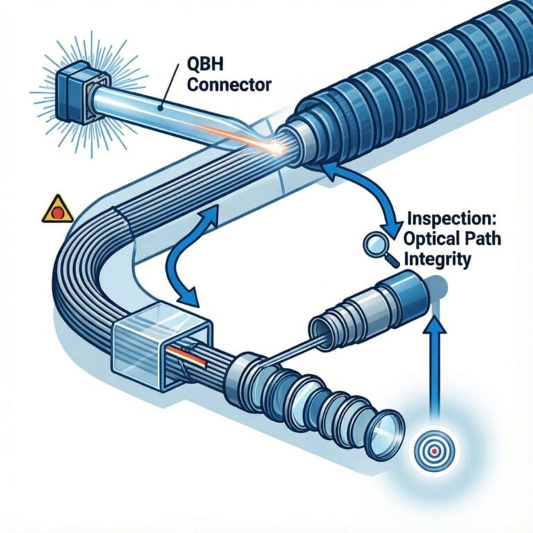
How 1,064nm Fiber Laser Wavelength Improves Tracking Accuracy
The fiber laser’s 1,064nm wavelength offers a tracking advantage over CO₂: it can share optical path components with the tracking sensor. Because both the processing beam and the sensor’s structured light operate in the near-infrared range, beam delivery optics can be designed with a coaxial camera port that views the weld zone directly through the focusing lens — eliminating parallax error between what the sensor sees and what the laser hits. CO₂ systems at 10,600nm require separate sensor mounting with an offset, introducing calibration drift as the robot arm heats and expands during production.

Applications and Industry Impact
Tube and pipe mills: HF-welded tube production lines running at 30–120 m/min use seam tracking to keep the weld on the strip edge within ±0.1mm. Fiber laser seam tracking replaces the induction coil feedback loop, improving response time from 50ms to under 10ms — critical when the mill accelerates from threading speed to full production.
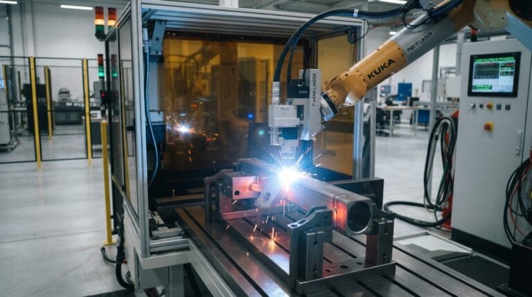
Automotive body-in-white: Laser brazing of roof-to-side-panel joints requires seam tracking that follows a 3D contour while the robot moves at 80–120 mm/s. Modern profilometry sensors track the joint in all six degrees of freedom simultaneously, compensating for both part-to-part variation and fixture tolerance stack-up.
Pressure vessel longitudinal seams: On 6–12m long shell courses rolled from 10–50mm plate, the weld gap can vary from 0 to 2mm along the seam due to rolling tolerance. Seam tracking with adaptive fill adjusts both position and laser power to maintain consistent penetration despite gap variation — eliminating the manual tack-and-measure step that previously added 20–30 minutes per vessel.
Best Practices for Laser Welding with Automated Seam Tracking
1. Calibrate at temperature. Run the robot through a warm-up cycle before calibrating the sensor — thermal expansion of the robot arm changes the TCP (tool center point) by 0.05–0.15mm, enough to shift the weld off a 0.2mm gap.
2. Validate on scrap first. Every new batch of material should get a test seam on a scrap piece cut from the same plate or coil. Surface condition (mill scale, oil, rust) affects sensor contrast — what worked on clean sheet may fail on hot-rolled plate with scale.
3. Monitor the tracking confidence signal. Most sensors output a confidence metric (0–100%) per frame. Set an alarm threshold at 70% confidence — if the sensor loses the seam for more than 100ms, pause the weld rather than producing a scrap part.
4. Clean the sensor window. Welding fume deposits on the sensor lens reduce contrast within 2–4 hours of continuous production. Cross-jet air knives and periodic automatic lens cleaning cycles are standard on production systems.
Intouchray’s Approach to Integrated Seam Tracking
Intouchray fiber laser welding systems support integration with leading seam tracking sensors through standard industrial communication protocols. All systems feature positioning accuracy of ±0.03mm and beam quality M² ≤ 1.1 — the baseline precision that makes seam tracking effective. Available laser sources (IPG, Raycus, MAX) at power ranges from 1kW to 6kW cover the full range of joint geometries and material thicknesses.
For manufacturers evaluating automated welding solutions, Intouchray provides application engineering support including joint design review, sensor compatibility assessment, and pre-purchase weld sample validation with your specified material and joint configuration.
Frequently Asked Questions
What is the maximum welding speed for reliable seam tracking?
With modern laser profilometry sensors operating at 200 Hz, reliable tracking is achievable at welding speeds up to 3 m/min on well-prepared joints. Beyond this, the sensor frame rate becomes the limiting factor — the robot moves more than 0.25mm between sensor frames, which may be larger than the allowable tracking error for thin-gauge joints. Higher-speed applications can use dual-sensor configurations or predictive tracking algorithms that extrapolate the seam path between sensor frames.
Does seam tracking work on reflective materials like aluminum?
Yes, but sensor settings must be tuned for the higher reflectivity. Laser profilometry sensors use blue or green laser diodes (405–520nm) specifically to handle reflective surfaces — these shorter wavelengths are less sensitive to the specular reflection that saturates red laser sensors on aluminum and copper. Intouchray’s application engineering team can recommend sensor configurations for specific material and surface condition combinations.