Non-Destructive Testing (NDT) of Laser Clad Layers: Techniques for Detecting Porosity, Cracks, and Delamination
The success of any high-power laser cladding application (Article #01-04, #08) ultimately hinges on one factor: quality assurance. When repairing a multi-million dollar turbine blisk (Article #16) or hardfacing a critical mining tool (Article #13), there is zero tolerance for defects. A hidden crack or a pocket of porosity can compromise the entire component, leading to catastrophic in-service failure.
Because laser cladding creates a distinct, often heterogeneous microstructure at the bond interface (Article #11), specialized inspection is required. This is where Non-Destructive Testing (NDT) is indispensable. NDT allows manufacturers to inspect the internal integrity of the clad layer and the bond line without damaging the high-value finished part. For laser cladding, three primary NDT techniques dominate, each designed to detect specific defect types.
1. Liquid Penetrant Testing (PT / Dye Penetrant)
Liquid Penetrant Testing is the most fundamental and widely used NDT method for laser cladding, primarily because it is fast, inexpensive, and highly effective at detecting surface-breaking defects.
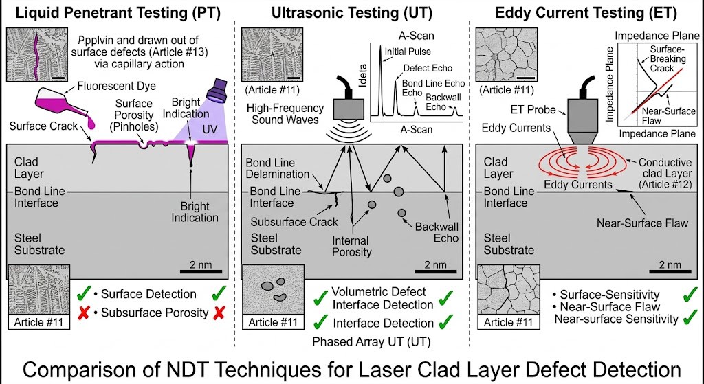
Principle: A highly visible or fluorescent dye is applied to the clean clad surface. After a defined ‘dwell time’, the excess surface dye is removed. A ‘developer’ is then applied, which draws any trapped dye out of surface defects via capillary action, creating a brightly colored indication.
What it Detects: PT is excellent for finding surface cracks (especially hot cracks or fatigue cracks), surface-breaking porosity (pinholes), and incomplete fusion defects that reach the outer surface.
Limitation: It cannot detect subsurface defects or delamination at the bond line.
2. Ultrasonic Testing (UT / Phased Array UT)
Ultrasonic Testing is the definitive volumetric inspection method for laser cladding, crucial for verifying the integrity of the critical bond line (Article #11).
Principle: A transducer introduces high-frequency sound waves into the clad layer. These waves travel through the material. When they encounter an interface (like the clad-substrate bond line) or an internal defect, a portion of the sound energy is reflected back to the transducer and analyzed.
What it Detects: UT is highly sensitive and is the primary method for detecting subsurface flaws, especially delamination (lack of metallurgical bond) at the substrate interface. It also detects subsurface porosity, inclusions (Article #03), and internal cracks. Advanced techniques like Phased Array UT (PAUT) use multiple transducers to create detailed 2D or 3D images of the clad layer’s internal structure.
Critical For: Bond line verification, particularly where high tensile residual stresses exist (Article #17) or low-dilution parameters (Article #04) were used.
3. Eddy Current Testing (ET)
Eddy Current Testing is a highly specialized NDT technique used primarily on conductive materials for detecting surface and near-surface defects and verifying conductive properties.
Principle: An alternating current flows through a coil, generating an oscillating magnetic field. When this coil is brought near a conductive material (like an Inconel clad layer, Article #12), it induces localized circular currents called ‘eddy currents’. Cracks, porosity, or changes in material properties disrupt these currents, which is detected as a change in the coil’s electrical impedance.
What it Detects: ET is extremely sensitive to surface and very shallow subsurface (near-surface) cracks and porosity. It is often faster than PT and requires less surface preparation. It can also be used to verify the thickness of the clad layer or check for conductive property variations (e.g., confirming the presence of WC particles in an MMC, Article #13).
Critical For: High-speed surface inspection of conductive superalloy cladding.
Summary: NDT Matrix for Laser Cladding Defects
To ensure comprehensive quality assurance, a combination of NDT methods is typically employed, creating a robust inspection matrix tailored to the potential defects of the specific application:
| Defect Type | Likely Location | Recommended NDT Method(s) | Article Context |
| Surface Cracks | Outer Surface | PT, ET | Bond Failure (Article #11, #17) |
| Porosity (Pinholes) | Outer Surface / Subsurface | PT (surface), UT, ET | Parameter Optimization (Article #04, #09) |
| Delamination | Bond Line Interface | UT / PAUT | Interface Metallurgy (Article #11) |
| Subsurface Cracks | Internal Clad Layer | UT | Stress Management (Article #17) |
| Inclusions | Internal Clad Layer | UT, ET | Powder Contamination (Article #03) |
| Lack of Fusion | Substrate Interface | UT | Heat Input Control (Article #04) |
Conclusion
Validating the integrity of a laser clad layer is not optional; it is the cornerstone of responsible additive repair and manufacturing. By meticulously applying Non-Destructive Testing techniques—specifically PT for surface flaws, UT for subsurface and bond line delamination, and ET for high-speed near-surface inspection—manufacturers can unlock the full potential of high-power laser cladding. This rigorous quality assurance ensures that every component, from a critical aerospace blisk to a heavy-duty mining tool (Article #13, #16), enters service with verified metallurgical bonds and defect-free microstructures (Article #11), guaranteeing performance and safety in the world’s most demanding industrial environments.
Frequently Asked Questions
What is the minimum detectable crack width your NDT system can reliably identify in a laser clad layer?
Our phased array ultrasonic testing (PAUT) system can consistently detect surface and sub-surface cracks with a width as small as 50 microns (0.05 mm) in Inconel 625 clad layers up to 5 mm thick, assuming a signal-to-noise ratio of at least 6 dB.
What is the maximum allowable porosity level your inspection can quantify, and what is the typical accuracy?
We can detect and map porosity down to 0.2% of the clad volume, with a sizing accuracy of ±0.1% for pores larger than 100 µm in diameter when using our laser-ultrasound (LUS) system at a scanning resolution of 0.5 mm.
Can your system detect delamination between the clad layer and the substrate, and what is the minimum debond area it can resolve?
Yes, our system detects delamination via ultrasonic C-scan imaging at 15 MHz. It can resolve a debond area as small as 1.5 mm² (e.g., a 1.4 mm circular flaw) with a false call rate under 2% on steel substrates with a 3 mm clad thickness.
What is the maximum inspection speed per square meter for a typical laser clad component?
For a 2 mm thick Stellite 6 clad layer on a 10 mm steel base, our automated robotic system achieves a scan speed of 0.8 m² per hour at a 1.0 mm step resolution, including real-time data processing and defect mapping.
What is the typical cost per linear meter for NDT inspection of a laser clad shaft?
For a 300 mm diameter shaft with a 4 mm clad layer, the standard inspection cost is approximately $45 per linear meter when using our phased array system, including a detailed digital report with defect coordinates and sizing data.
What certification or standards does your NDT process comply with for aerospace-grade laser cladding?
Our procedures are qualified to ASTM E2700 and NAS 410 standards, and we provide a 95% probability of detection (POD) for a 0.3 mm deep crack at a 95% confidence level, as validated by a recent round-robin test with 12 aerospace suppliers.