Remanufacturing High-Value Aerospace Components: Laser Cladding of Turbine Blade Tips and Blisks
In the aerospace industry, the cost of engine components is astronomical. A single high-pressure turbine blade can cost thousands of dollars, and an integrated blisk (bladed disk) can be worth hundreds of thousands. These components operate under extreme conditions—intense heat, centrifugal force, and erosion from high-velocity gases and volcanic ash. This environment leads to inevitable surface degradation, particularly on critical areas like turbine blade tips and leading edges.
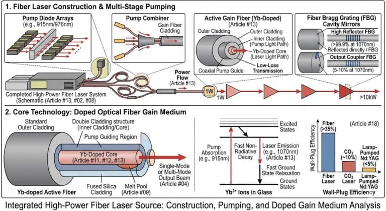
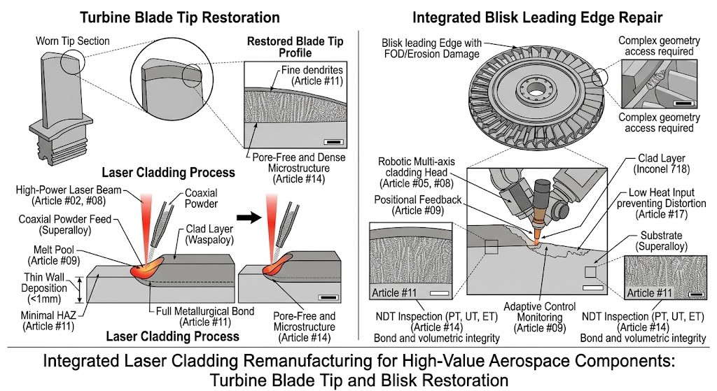
Scrapping these parts due to localized wear is economically unsustainable. Traditional repair methods, such as TIG welding, introduce excessive heat, leading to distortion and metallurgy-damaging Heat Affected Zones (HAZ) in sensitive superalloys (Article #11). High-power fiber laser cladding (Article #02, #08) has emerged as the premier technology for remanufacturing these high-value assets, offering unmatched precision, minimal heat input, and the ability to deposit metallurgically bonded (Article #11) superalloys (Article #12) with flawless quality.
- The Challenges: Blade Tip and Blisk Geometry
Remanufacturing aerospace components requires specialized approaches tailored to unique geometries:
Turbine Blade Tip Restoration
Turbine blade tips must maintain a precise, minimal clearance with the engine casing to maximize fuel efficiency. As tips wear down (tip recession), engine performance drops and fuel consumption rises.
The Geometry: Repairing tips involves cladding onto a thin, sharp wall (sometimes <1mm thick), often on complex 3D helical shapes.
The Laser Cladding Advantage: The focused energy profile of a single-mode fiber laser (Article #02) is essential here. Robotic systems (Article #05) guide the laser head precisely over the blade tip path, depositing thin, dense layers (Article #04) of nickel- or cobalt-based superalloy (Article #12) to rebuild the exact height and profile. The low heat input prevents thin-wall distortion (Article #17) or “burn-through,” critical requirements for this application.
Integrated Blisk leading Edge Repair
A blisk is a single, machined component combining the rotor disk and multiple blades, eliminating the need for individual blade attachment. While highly efficient, damage to a single blade leading edge (due to foreign object damage (FOD) or erosion) previously meant replacing the entire blisk.
The Geometry: Blisk blades are aerodynamically complex and closely spaced, making access for repair challenging.
The Laser Cladding Advantage: Specialized robotic cladding cells (Article #08), often featuring multi-axis motion and synchronized positioners, are designed to access the tight blisk leading edges. The high degree of accuracy ensures that only the worn edge material is deposited. Crucially, the process minimizes the HAZ (Article #11) in the complex nickel-base or titanium-base blisk superalloys (Article #12), maintaining the structural integrity of the entire component, which is paramount for flight safety. Adaptive control systems (Article #09) play a key role in monitoring real-time heat buildup on these critical thin sections.
- High-Performance Alloys and Superior Bonding
The critical demand of aerospace is metallurgical integrity. Laser cladding meets this requirement through:
Optimized Superalloys for Aerospace Service (Article #12)
Components are cladded using advanced nickel- (e.g., Inconel 718, Waspaloy) or cobalt-base (e.g., Stellite 6) superalloys, carefully selected to match or exceed the mechanical and corrosion properties of the substrate (Article #12). These materials must retain noble strength and oxidation resistance at temperatures approaching the alloy’s melting point.
Flawless Metallurgical Bond (Article #11)
Unlike mechanical bonds formed by thermal spray (Article #01), laser cladding creates a full metallurgical bond with the substrate. As detailed in Article #11, precise heat control (often with adaptive feedback, Article #09) ensures the perfect degree of interface melting, resulting in a joint with full material density and excellent fatigue strength, essential for components experiencing extreme vibrational loads in service.
- Integrated Quality Assurance (Article #14)
Given the high-stakes nature of aerospace flight, all remanufactured blisks and blade tips must undergo exhaustive quality verification. Standardized Non-Destructive Testing (Article #14)—including Liquid Penetrant (PT) for surface flaws, Ultrasonic (UT) for volumetric integrity and bond verification, and Eddy Current (ET) for near-surface flaws—is mandatory. Advanced techniques like Phased Array UT and even Digital Radiography are increasingly used to create detailed 3D maps of the internal structure, confirming the dense, pore-free, and metallurgically sound nature of the clad layer (Article #11) before the component is returned to service.
Conclusion: Driving Sustainable Aerospace Efficiency
High-power fiber laser cladding is revolutionizing aerospace sustainability by transforming remanufacturing from a trial-and-error process into a precise, reliable science. By extending the life of high-value, critical assets like turbine blade tips and integrated blisks, aerospace companies can unlock immense economic value, reducing part replacement costs and lead times. This technology doesn’t just return components to flight; it ensures they perform with noble efficiency and reliability, making it an indispensable pillar of modern, cost-effective, and safe aerospace manufacturing.
Image Attachment
Technical Comparison
| Technical Parameter | Standard 4kW Fiber Laser System | High-Power 10kW Multi-Mode Fiber Laser System |
|---|---|---|
| Max Laser Output Power | 4 kW | 10 kW |
| Cladding Travel Speed | 0.5 – 1.2 m/min | 1.5 – 3.5 m/min |
| Powder Feed Rate | 5 – 15 g/min | 15 – 45 g/min |
| Single-Pass Layer Thickness | 0.3 – 0.6 mm | 0.8 – 1.5 mm |
| Positioning & Tracking Accuracy | ±50 µm | ±15 µm |
| Heat Affected Zone (HAZ) Depth | 0.4 – 0.8 mm | 0.15 – 0.35 mm |