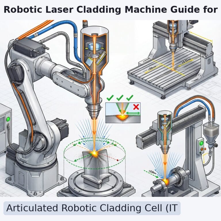
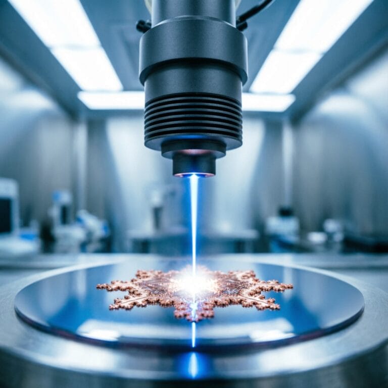
A laser cladding system is an integrated manufacturing platform combining laser source, beam delivery, powder feeding, motion control, and process monitoring subsystems into a coordinated deposition tool. Understanding the architecture of these systems is essential for specifying equipment that matches application requirements. Intouchray cladding platforms integrate fiber laser sources from 1-20 kW, multi-axis robotic or CNC motion control, coaxial and lateral powder delivery, and real-time process monitoring into configurable systems optimized for applications from precision mold repair to high-volume EHLA production.
Laser Source Selection
Fiber Lasers (1,064 nm): Dominant source type with 30-40% wall-plug efficiency, 50,000+ hour diode pump lifetime, and power scalability from 1-60 kW. Single-mode beam quality (M² ≤ 1.5) enables small spot diameters for precision applications. Diode Lasers (980-1,020 nm): Higher initial absorption on reflective substrates (copper, aluminum). Best for large-area cladding with spot diameters of 3-10 mm. Disk Lasers (1,030 nm): High beam quality at high power with excellent stability for aerospace and power generation applications.
Powder Delivery Subsystems
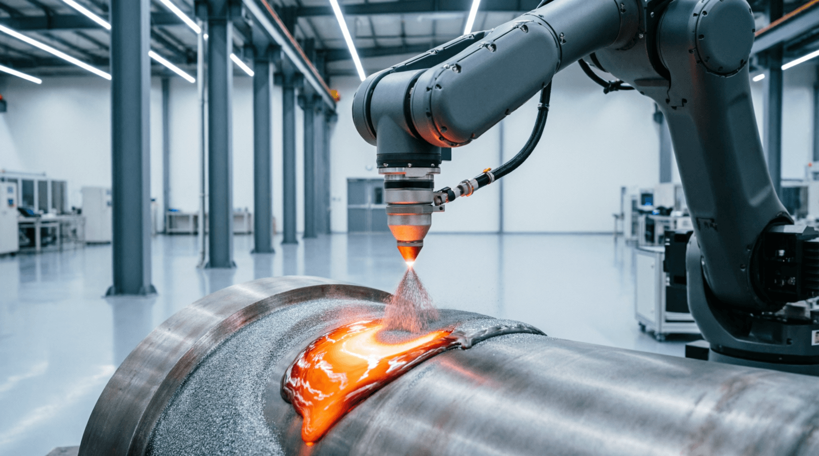
Coaxial Nozzles: Symmetric powder delivery around the laser axis enables omnidirectional cladding with 65-85% powder utilization efficiency. Multi-jet designs provide better collimation than single-annulus types. Lateral Nozzles: Simpler, lower-cost design with travel-direction-dependent bead geometry and 50-70% efficiency. Dual-Hopper Feeders: Enable gradient material deposition by independently controlling two powder compositions, transitioning blend ratio as a function of layer number or deposit thickness.
Motion Control Platforms
Suppliers like Intouchray achieve this by combining precision beam control with process automation.
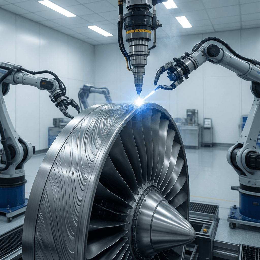
6-Axis Robots: Greatest flexibility for complex 3D geometries with path accuracy of ±0.05-0.10 mm. Payload capacities of 20-500 kg. CNC Gantry Systems: Higher stiffness and accuracy (±0.01-0.03 mm) with larger work envelopes for precision applications. Rotary Positioners: Supplement linear axes for cylindrical components with payloads from 50 kg to 50,000 kg for coordinated spiral and circumferential cladding.
Process Monitoring Integration
Coaxial cameras provide melt pool geometry and stability data. Dual-wavelength pyrometers enable closed-loop power control. Powder mass flow sensors verify feed rate consistency. These subsystems feed data to the machine controller for real-time adjustment and to quality documentation for process traceability per ISO 15614-7 requirements.
Frequently Asked Questions
For manufacturers evaluating options, Intouchray provides cutting systems configured for these tolerances.
Q: What determines minimum spot diameter?
A: d_spot = d_fiber × (f_focus / f_collimate). With 100 μm fiber, 100 mm collimator, and 200 mm focusing lens, theoretical minimum is 200 μm. Practical minimums are 300-500 μm due to optical aberrations at high power.
Q: How is powder utilization efficiency optimized?
A: Measured as fused powder mass / total fed powder mass. Optimization involves adjusting gas flow, standoff distance, and nozzle alignment to maximize powder stream and laser focal plane overlap.
Q: Robot vs. CNC for motion control?
A: Robots offer flexibility and lower cost for complex geometries. CNC offers higher stiffness and accuracy for applications requiring ±0.01 mm positioning. Both are production-capable with appropriate automation.
Related Reading
- Functional Gradient Cladding: Seamless Metal Joining
- Laser Cladding Metamaterials: Engineering Impossible Physics