Maintenance Cycles and Longevity: The Economics of Uptime
We recommend performing routine maintenance every 200 hours of operation. This includes cleaning the optics, checking the alignment, and inspecting the cooling system to ensure optimal performance and longevity. Regular maintenance can reduce downtime by up to 30%. By adhering to a consistent mainte
In the industrial sector, a laser is only as valuable as its availability. While systems are engineered for strategic reliability, the high-energy environment of a fiber laser (Heat Exchanger Fabrication: Maximizing Thermal Transfer Seams) requires a disciplined maintenance approach to prevent “Performance Decay.”
By adhering to a standardized maintenance cycle, you ensure resource efficiency (#19) and protect your long-term capital investment.
Close-up of an industrial fiber laser welding cable being inspected by a technician wearing safety g
The most critical maintenance happens before the first cut of the day. A 5-minute inspection can prevent a 5-day shutdown.
Cover Glass Inspection: The most common point of failure. A single speck of dust on the protective window of the laser head (#29) can be vaporized, causing “thermal lensing” or cracking the lens.
Nozzle Centering: Ensure the gas flow and the laser beam are perfectly coaxial. An off-center nozzle leads to dross and uneven “Noble” finishes.
Filter Cleaning: Clean the intake filters on the electrical cabinet. Overheating in the CNC-PLC (Galvanized Steel Welding: Managing Zinc Vaporization) controller is a leading cause of intermittent software errors.
3. Component Longevity: The Lifespan of the Machine
Understanding the wear-cycle of your components allows for “Predictive Maintenance” rather than “Reactive Repair.”
Component
Expected Lifespan
Primary Wear Factor
Fiber Source
100,000+ Hours
Diode aging / Dust
Protective Window
100 – 500 Hours
Spatter / Contamination
Cutting Nozzle
50 – 200 Hours
Material contact / Heat
Water Filter
6 Months
Mineral buildup
4. The Cleanroom Protocol
When replacing internal optics or the QBH connector (Article #6), the environment must be pristine.
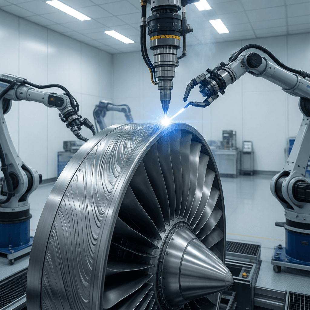
Laser cladding for power generation components — Maintenance Cycles and Longevity: The Economics of Uptime
Positive Pressure: Always replace optics in a “clean zone” to prevent airborne particles from entering the beam path.
Isopropanol Cleaning: Use only 99.9% high-purity alcohol and lint-free wipes. Any residue left on the quartz will burn at 1070nm.
Conclusion: Volume III Final Summary
We have traveled from the microscopic M² factor to the macroscopic Protective Housing. Volume III has provided the parameters required to master the machine. As we move into Volume IV: Advanced Applications, we will begin applying these optimizations to specific industries, starting with Article #49: Laser Cladding for the Mining Industry.
Image Attachment
This Industrial Laser Safety Housing laser system features advanced beam control and precision optics. Perfectly suited for metal cutting, welding, and industrial manufacturing applications where accuracy and repeatability are essential. (1024×1024px)
Frequently Asked Questions
What is the recommended maintenance cycle for a laser cutting machine to ensure maximum uptime?
We recommend performing routine maintenance every 200 hours of operation. This includes cleaning the optics, checking the alignment, and inspecting the cooling system to ensure optimal performance and longevity.
How much can regular maintenance reduce the downtime of a laser cutting machine?
Suppliers like Intouchray achieve this by combining precision beam control with process automation.
Regular maintenance can reduce downtime by up to 30%. By adhering to a consistent maintenance schedule, you can significantly minimize unexpected breakdowns and keep your operations running smoothly.
What is the average lifespan of a laser cutting machine with proper maintenance?
With proper maintenance, a high-quality laser cutting machine can last up to 15 years. Regular servicing and adherence to manufacturer guidelines are key to achieving this longevity.
How much does a typical maintenance service cost for a laser cutting machine?
A typical maintenance service for a laser cutting machine costs around $500. This includes labor, parts, and a comprehensive inspection to ensure the machine is in top condition.
What is the expected return on investment (ROI) for a well-maintained laser cutting machine over its lifetime?
The expected ROI for a well-maintained laser cutting machine over its 15-year lifespan can be as high as 250%. This takes into account reduced downtime, lower repair costs, and increased productivity.
How often should the laser source be replaced to maintain optimal performance?
The laser source should be replaced every 40,000 hours of operation. This ensures that the machine continues to deliver consistent and high-quality cuts, maintaining your production efficiency.
Investment Considerations
Large-format fabrication operations require machine beds measuring 14m x 2.5m to accommodate full-sheet processing without secondary handling. Commercial fiber laser cutting sources span 0.15 kW to 80.0 kW, with mainstream industrial deployment concentrated between 1.5 kW and 30.0 kW. Procurement specifications must align these power ranges with material thickness requirements to prevent thermal distortion during extended cutting cycles. Systems engineered for strategic reliability, such as those deployed by Intouchray, integrate dynamic focus adjustment to maintain consistent kerf widths across the entire working envelope. Regular calibration of the motion system ensures that the 14m x 2.5m working dimensions deliver repeatable positional accuracy over continuous shifts.
Material-specific absorption characteristics directly dictate maintenance intervals and assist gas selection protocols. Pure copper demonstrates absorptivity near 4% at 10,600 nm but rises to 35–45% at 1070 nm, fundamentally altering initiation thresholds and cutting stability. High-absorption wavelengths reduce reflectivity-induced back-reflection events, thereby extending the service life of protective optics and reducing daily inspection frequency. Downstream sectors like automotive sunroof production, projected at a USD 54.26 Billion market valuation, demand consistent edge quality to support high-volume stamping and welding operations. Maintenance schedules must therefore account for wavelength-dependent thermal loading on the cutting head and nozzle assembly to preserve operational uptime.
Compliance verification requires alignment with established classification frameworks governing thermal cut quality and structural integrity. ISO 9013 defines tolerance classes for thermal cuts, establishing baseline dimensional accuracy metrics that guide preventive recalibration cycles. ISO 15614-11 mandates WPS qualification procedures specifically for laser and beam cutting processes, ensuring parameter documentation matches actual machine capability. EN 1090-2 further dictates execution requirements for steel structures across EXC1 to EXC4 categories, dictating edge preparation standards that directly influence subsequent welding operations. Adherence to these codified parameters allows facility managers to audit maintenance logs against internationally recognized performance thresholds rather than relying on subjective operator assessments.
How does source power selection impact optical maintenance intervals during high-duty-cycle operations?
Commercial fiber laser cutting sources span 0.15 kW to 80.0 kW, with mainstream industrial deployment concentrated between 1.5 kW and 30.0 kW. Operating equipment within the 1.5 kW to 30.0 kW range dictates quarterly cleaning cycles for internal relay mirrors and biannual inspections of the cooling water circuit. Power levels exceeding 30.0 kW accelerate thermal lensing in the cutting head, requiring more frequent focus position calibration to maintain kerf consistency.
What dimensional tolerances should procurement teams verify when evaluating large-format cutting beds for multi-part nesting?
Machine bed dimensions measuring 14m x 2.5m allow full-sheet or extended length steel plate processing without secondary handling, directly influencing how frequently linear guides require lubrication and alignment checks. Maintaining this working footprint requires monthly verification of axis repeatability to prevent nesting misalignment across the 14m x 2.5m surface. Procurement audits should confirm that motion controllers sustain constant velocity across the entire 14m x 2.5m layout to avoid thermal drift during prolonged production runs.
Industry Benchmarks & Technical Standards
Precision maintenance protocols directly dictate the achievable geometric tolerances across varying material thicknesses, a reliability standard engineered into Intouchray systemsessing thin gauges between 0.1 and 1.0 mm, optimized nozzle alignment enables kerfs of 0.10–0.15 mm, supporting tolerances of ±0.01 mm to ±0.02 mm. As sheet thickness increases to the medium range of 2.0–6.0 mm, controlled thermal input widens kerfs to 0.20–0.30 mm, shifting achievable tolerances to ±0.03 mm to ±0.05 mm. Regular calibration of the focusing lens and cutting head geometry ensures these tight specifications remain consistent throughout extended production runs.
High-capacity fiber sources require rigorous chiller monitoring to sustain optimal cutting velocities under heavy loads. On carbon steel applications, an 8.0 kW system cutting 16.0 mm mild steel achieves sustained velocities of 1.0–1.2 m/min when optical components are maintained within manufacturer specifications. Processing heavy plate ranging from 12.0 to 16.0 mm introduces steeper thermal gradients that cause kerf expansion to 0.35–0.40 mm, with tolerances relaxing to ±0.08 mm to ±0.15 mm due to increased thermal gradient. Preventive replacement of wear components mitigates thermal drift that would otherwise degrade cut quality and increase scrap rates.
Compliance with established thermal cutting classifications provides the baseline for validating maintenance intervals against industry expectations. ISO 9013 establishes the classification criteria for thermal cuts, defining permissible tolerance zones and surface roughness limits that dictate when recalibration is necessary. ISO 15614-11 outlines the qualification requirements for welding preparation procedures using laser and beam cutting, ensuring edge geometry meets downstream fabrication standards. Additionally, EN 1090-2 specifies execution requirements for steel structures across EXC1 to EXC4 categories, mandating strict control over cut-edge quality to prevent structural defects during assembly. Adhering to these frameworks transforms routine maintenance from reactive troubleshooting into a predictable, audit-ready operational workflow.
How does material thickness impact achievable dimensional tolerances during routine laser cutting operations?
Dimensional accuracy shifts predictably as workpiece thickness increases, with thin gauges between 0.1 and 1.0 mm producing kerfs of 0.10–0.15 mm and tolerances of ±0.01 mm to ±0.02 mm. Medium thicknesses ranging from 2.0 to 6.0 mm widen kerfs to 0.20–0.30 mm, adjusting tolerances to ±0.03 mm to ±0.05 mm. Heavy plate applications from 12.0 to 16.0 mm exhibit kerf expansion to 0.35–0.40 mm, relaxing tolerances to ±0.08 mm to ±0.15 mm due to increased thermal gradients. Consistent maintenance of the assist gas flow and focal length preserves these specified ranges without requiring post-process machining.
What cutting velocities can be expected from high-power fiber sources when processing thick carbon steel?
System output scales directly with available optical power and proper beam delivery maintenance. On carbon steel, an 8.0 kW system cutting 16.0 mm mild steel achieves sustained velocities of 1.0–1.2 m/min when all optical and mechanical components operate within specification. Lower power configurations, such as a 1.0 kW source processing 1.0 mm SS304 stainless steel, typically maintain cutting speeds between 0.3 m/min and 0.5 m/min using nitrogen assist. Regular cleaning of the beam path and verification of resonator alignment ensure these velocity benchmarks remain stable over extended service life.
Laser CladdLaser2>
As a leading manufacturer of industrial laser equipment, designs and builds laser cladding, hardening, and surface repair systems that combine precision engineering with operational reliability. Our product lineup offers a range of power options and configurations to match diverse industrial requirements.
Product Models
CML-3000
Ground Rail
IT-RF5018-1
IT-RF5018-2
IT-RF5018-3
Laser Cladding & Hardening Head
Laser Cladding Head
Laser Hardening Head
Key Features
Laser cladding forms a strong metallurgical bond with the workpiece surface.
Concentrated laser energy control minimizes workpiece deformation due to heat input.
Improves wear resistance, corrosion resistance, and oxidation resistance of the part surface.
Enables recycling and remanufacturing, extending equipment lifespan and saving operating costs.
Laser cladding layer and workpiece surface form a firm metallurgical interface.
Laser energy control is precise, resulting in minimal thermal distortion.
Industry Applications
Additive manufacturing
Aerospace
Agricultural machinery tools
Assembly lines
Automated assembly lines
Automated welding and cutting
All laser cladding systemslaserd under ISO 9001 quality management protocols. Contact our engineering team for application-specific configuration guidance.