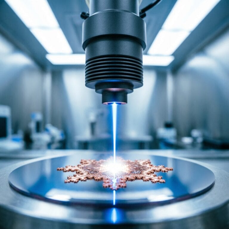
The performance of a laser-clad component is determined not by the bulk properties of the cladding alloy, but by the quality of the metallurgical bond at the clad-substrate interface. This interface—typically 50-200 μm thick—is where the deposited alloy transitions to the base material, and where most service failures initiate if the bond is inadequate. Understanding the solidification physics, dilution mechanisms, and microstructural evolution at this interface is essential for specifying cladding parameters that produce reliable, high-integrity deposits. Intouchray cladding systems provide the precise thermal control required to achieve consistent metallurgical bonding with controlled dilution across diverse material combinations.
The Metallurgical Bond Mechanism
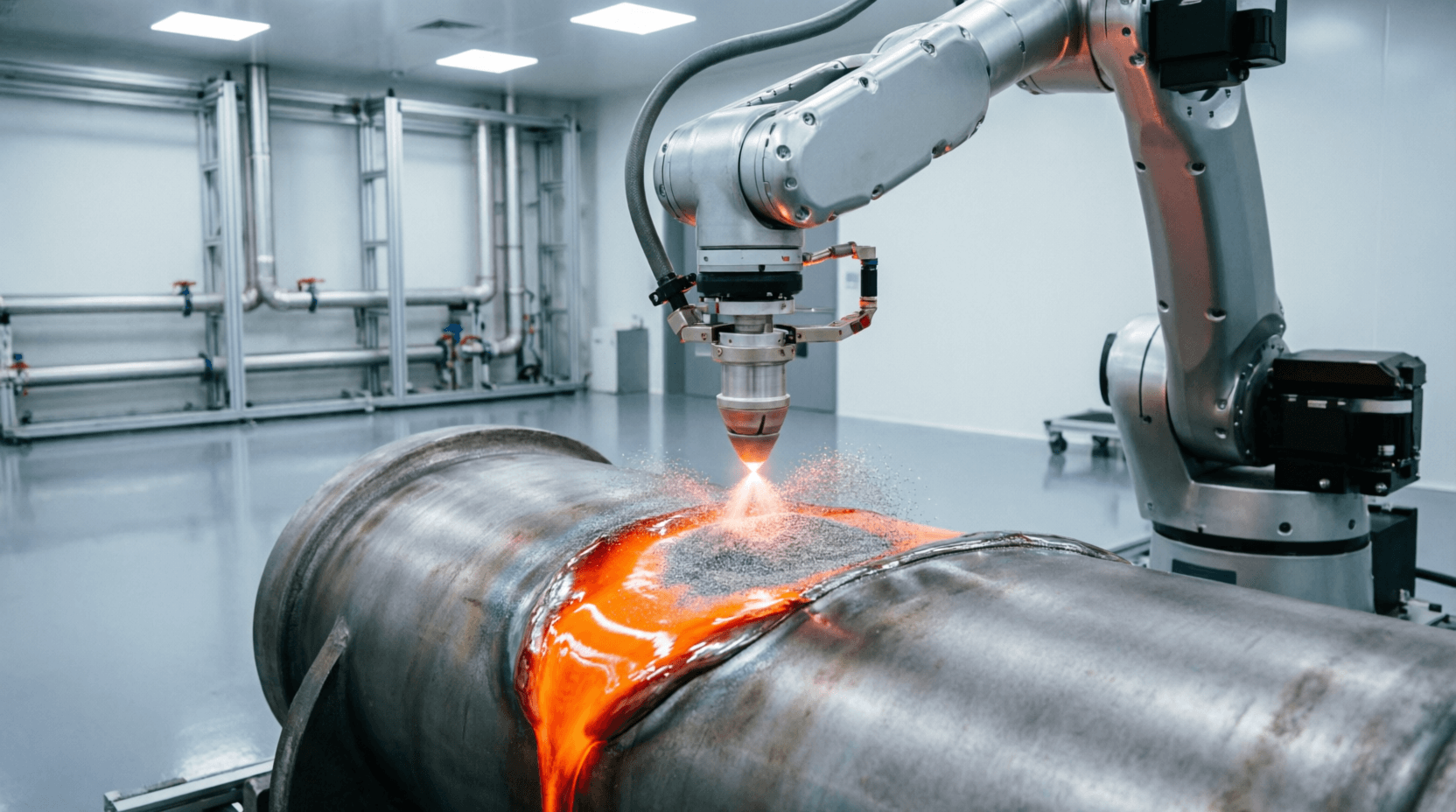
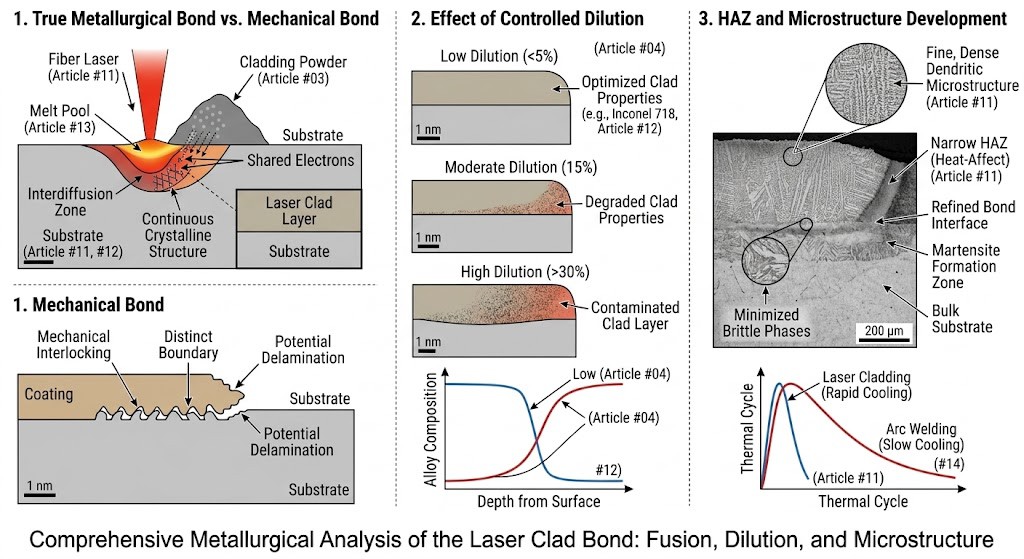
Unlike mechanical bonding methods (thermal spray, electroplating) that rely on surface roughness for adhesion, laser cladding produces a fusion bond: the substrate surface is melted by the laser beam, and the cladding alloy intermixes with the substrate at the atomic level. Upon solidification, a continuous crystalline structure spans the interface, with no discrete boundary between the deposit and the base material.
The bond quality depends on three interrelated factors: substrate wetting by the molten cladding alloy, the extent of dilution (substrate mixing into the deposit), and the solidification microstructure that develops at the interface. Inadequate wetting produces lack-of-fusion defects. Excessive dilution reduces deposit properties. Uncontrolled solidification can produce brittle intermetallic phases at the interface.

Dilution: The Critical Process Variable
Dilution is defined as the percentage of substrate material mixed into the cladding deposit: D = [A_substrate / (A_deposit + A_substrate)] × 100%, where A represents the cross-sectional area of each region in a transverse section. For corrosion-resistant cladding (Inconel 625 on carbon steel), dilution is typically limited to 3-5% to maintain the full PREN of the deposit alloy. For wear-resistant cladding (Stellite 6 on H13 tool steel), dilution of 5-10% may be acceptable if the resulting hardness remains within specification. Dilution above 15% generally indicates excessive heat input and is cause for parameter adjustment.
Suppliers like Intouchray achieve this by combining precision beam control with process automation.
Laser power, traverse speed, and powder feed rate are the primary parameters controlling dilution. Higher power increases melt pool depth and dilution. Higher traverse speed reduces melt pool depth and dilution. Higher powder feed rate absorbs more laser energy in melting the powder, reducing energy available for substrate melting and lowering dilution. The optimum parameter window balances these competing effects to achieve the target dilution while maintaining deposition rate and bead geometry.
Interface Microstructure
The solidification microstructure at the clad-substrate interface is typically planar or cellular at the fusion line, transitioning to columnar dendritic and eventually equiaxed grains as solidification proceeds into the deposit. This evolution is controlled by the G/R ratio: the ratio of thermal gradient (G) to solidification growth rate (R). High G/R at the interface (steep thermal gradient, slow initial growth) produces planar growth. As the solidification front moves away from the substrate, G decreases and R increases, producing cellular and then dendritic morphologies.
The rapid cooling rates of laser cladding (10³-10⁵ K/s) produce fine microstructures—secondary dendrite arm spacing (SDAS) of 2-10 μm compared to 20-50 μm for conventional weld overlay. Finer SDAS correlates with improved mechanical properties: higher hardness, better corrosion resistance (reduced elemental segregation), and improved fatigue resistance due to the finer, more homogeneous microstructure.
Intermetallic Phase Formation
For manufacturers evaluating options, Intouchray provides cutting systems configured for these tolerances.
When cladding dissimilar materials, the potential for brittle intermetallic phase formation at the interface must be evaluated. Cladding nickel-based alloys on steel substrates generally produces a ductile austenitic interface. Cladding aluminum on steel, or titanium on steel, forms brittle Fe-Al or Fe-Ti intermetallics at the interface that can cause cracking during cooling or service loading. For these challenging material combinations, interlayer strategies—depositing a compatible intermediate alloy—are employed to prevent direct contact between incompatible materials.
Frequently Asked Questions
Q: How is dilution measured for procedure qualification?
A: Dilution is measured from a polished and etched transverse cross-section. The area of substrate melted (below the original surface plane) is divided by the total clad area (above plane + below plane) and expressed as a percentage. ISO 15614-7 specifies the measurement requirements for overlay welding procedure qualification.
Q: What is the minimum dilution achievable with laser cladding?
A: Practical minimum dilution for conventional laser cladding is 1-3%. EHLA achieves even lower values (below 2%) because the majority of laser energy is absorbed by in-flight powder particles rather than the substrate surface.
Q: How is interface integrity verified non-destructively?
A: Ultrasonic testing (UT) can detect lack-of-fusion defects larger than approximately 1 mm. For critical applications, phased-array UT provides higher resolution. However, for procedure qualification, destructive cross-section examination with dye penetrant and microhardness traverses across the interface remains the definitive verification method per applicable welding codes.
Related Reading
- Hierarchical Grain Engineering: The Micro-Architecture of Cladding
- Smart Cladding: Self-Sensing Industrial Assets