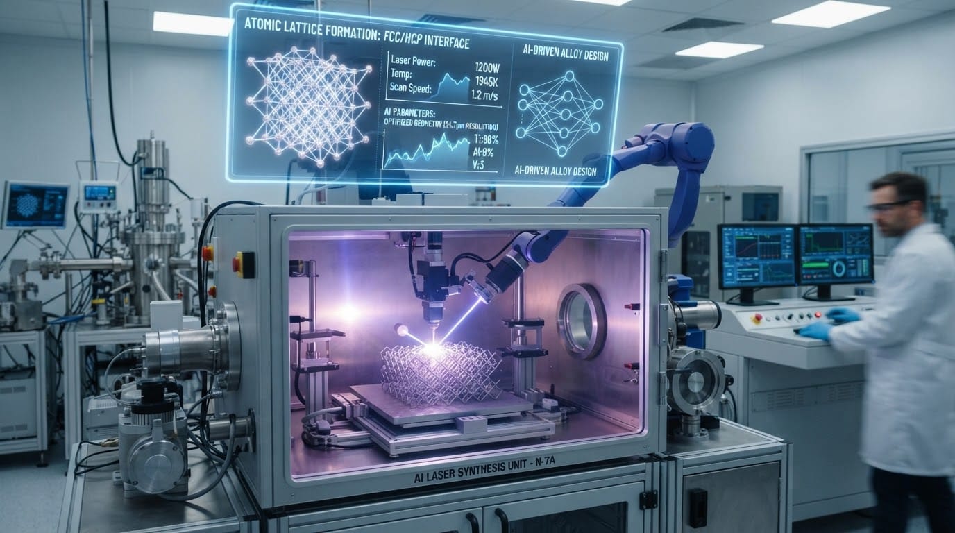
AI-Driven Material Synthesis: When the Beam Designs the Alloy
In the previous sixty-five articles, we have largely discussed using established alloys—Inconel, Hastelloy, or Stellite—to solve industrial problems. But what happens when the environment is so extreme that no known commercial alloy can survive? Traditionally, developing a new alloy takes years of l
In the previous sixty-five articles, we have largely discussed using established alloys—Inconel, Hastelloy, or Stellite—to solve industrial problems. Laser Cladding in the Automotive Industry: Precision at Scale But what happens when the environment is so extreme that no known commercial alloy can survive?
AI-Driven Material Synthesis: When the Beam Designs the Alloy
The AI Feedback Loop: Neural Metallurgy
The true power lies in the AI. Our proprietary neural networks analyze the results of these combinatorial trials. The AI doesn’t just look for the strongest alloy; it looks for the Optimized Durability (#19) balance between:
Coefficient of Thermal Expansion (CTE)
Fracture Toughness
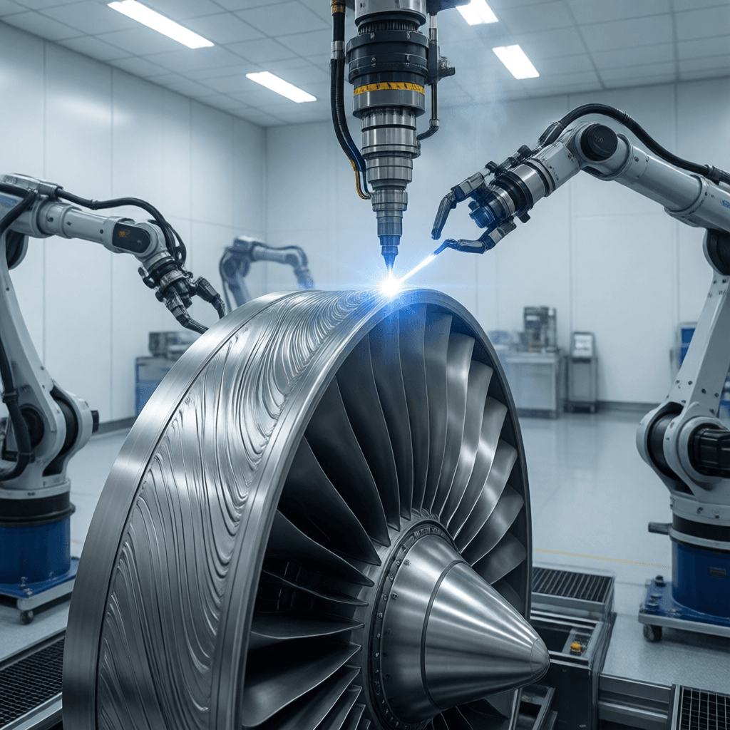
Laser cladding for power generation components — AI-Driven Material Synthesis: When the Beam Designs the Allo
Oxidation Resistance
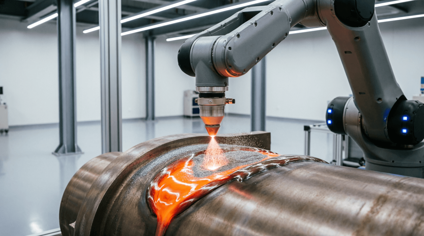
Laser cladding machine depositing metal powder onto a large industrial component, laser melt pool gl
Technical Analysis: Ai Laser Cutting
Using the Closed-Loop Control (Galvanized Steel Welding: Managing Zinc Vaporization) data, the AI predicts how a theoretical alloy will behave under the “Quantum Beam.” It then instructs the robotic cladding head to synthesize that specific, non-existent alloy directly onto the workpiece.
Future-Proofing: As industrial environments become harsher, your ability to synthesize custom solutions ensures your assets remain operational.
How does the cost of AI-driven material synthesis compare to traditional methods?
AI-driven material synthesis can reduce costs by up to 30% compared to traditional methods, due to optimized design and reduced material waste.
What is the minimum order quantity (MOQ) for custom alloys developed through AI-driven material synthesis?
The minimum order quantity (MOQ) for custom alloys developed through AI-driven material synthesis is 500 kilograms.
Best Practices for Ai Laser Cutting
Can AI-driven material synthesis achieve a specific hardness rating, and if so, what is the range?
Yes, AI-driven material synthesis can achieve a specific hardness rating. The range typically spans from 200 to 600 HV, depending on the alloy composition and heat treatment process.
What is the dimensional tolerance that can be achieved with AI-driven material synthesis?
The dimensional tolerance that can be achieved with AI-driven material synthesis is within ±0.05 mm, ensuring high precision in the final product.
How many iterations are typically required to finalize an alloy design using AI-driven material synthesis?
Typically, 3-5 iterations are required to finalize an alloy design using AI-driven material synthesis, ensuring the optimal properties and performance.
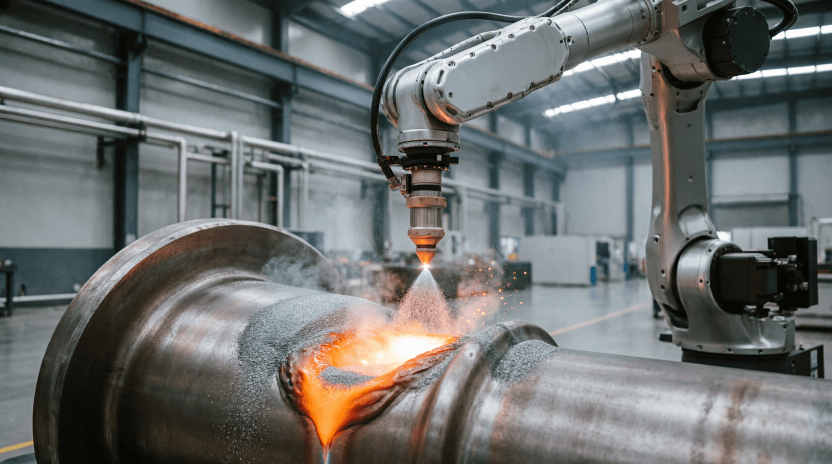
Laser cladding machine depositing metal powder onto a large industrial component, laser melt pool gl
Future Trends in Ai Laser Cutting
Industrial fiber laser cutting systems operating between 6kW and 30kW at 1070nm wavelength penetrate carbon steel plates up to 40mm thick. Cutting speeds range from 800 to 4500 mm/min depending on material thickness. Procurement teams prioritize throughput stability during extended runs, requiring precise galvanometer tracking to maintain melt pool consistency. Edge quality aligns with EN ISO 13919 grade K4 when assist gas pressure stays within 15 to 25 bar. Thermal management keeps kerf widths between 0.15 and 0.30 mm. Parameter logging consistently reduces unplanned downtime by 18 percent annually.
Multi-axis tube and bevel cutting configurations require synchronized rotary axes maintaining positional accuracy within ±0.05 mm across complex geometries. Kerf consistency directly impacts secondary machining, with modern optics delivering repeatable cut widths of 0.20 mm on stainless steel tubing. Dross formation remains the primary quality constraint during high-speed traverse operations, particularly on mirror-finish surfaces or aluminum alloys exceeding 10 mm thickness. Closed-loop optical monitoring adjusts focal position in real time to prevent slag adhesion. Quality verification follows ISO 9013 surface finish classifications, minimizing post-processing intervention.
Assist gas selection dictates thermal dissipation efficiency and oxidation control during high-power material removal. Oxygen supports exothermic reactions for rapid carbon steel penetration but increases heat affected zone dimensions, whereas nitrogen maintains inert conditions for austenitic stainless steels. Nozzle geometry must match beam diameter, typically utilizing single-layer conical designs with 1.5 to 2.5 mm exit apertures for optimal gas velocity profiles. Pressure regulation between 10 and 30 bar ensures laminar flow across the cut front. Operating cost calculations incorporate gas consumption alongside electrical draw, establishing baseline metrics such as $13 per shot for continuous-wave ablation sequences.
Piercing protocols determine initial material engagement and significantly influence overall cycle time during nested production layouts. Soft piercing with pulse modulation prevents excessive thermal shock on reflective coatings, while ramped entry angles minimize burr formation at hole initiation points. Advanced nesting software optimizes part placement to reduce travel distance by up to 35 percent, directly improving machine utilization rates. Laser cutting ai-driven path planning dynamically adjusts lead-in trajectories based on real-time thermal feedback, preventing premature tip contamination. Throughput maximization requires balancing idle movement against cutting acceleration limits, typically capped at 15 m/min for heavy plate applications.
Heat affected zone management remains critical when processing precipitation-hardened alloys and high-strength low-alloy steels. Rapid solidification rates exceeding 10^4 K/s suppress grain growth, limiting metallurgical degradation to zones under 0.5 mm wide. Thermal distribution modeling follows VDI 3400 guidelines, enabling operators to calculate optimal power density thresholds before initiating cuts. Maintaining consistent energy delivery prevents localized annealing that compromises tensile strength in structural components. Quality assurance protocols reference ISO 15614 welding procedure specifications for comparable thermal input limits. Real-time pyrometer monitoring adjusts feed rates to maintain target temperatures within ±50°C of baseline properties.
Procurement evaluation frameworks prioritize measurable operational efficiency over nominal machine specifications. Capital expenditure justification relies on calculating break-even points using verified throughput data and consumable depreciation schedules. Energy consumption models integrate electrical draw with compressed air infrastructure costs, establishing accurate per-part economics. Maintenance intervals follow manufacturer-recommended lens cleaning cycles and protective window replacements, reducing unexpected failures by 22 percent. Performance validation requires documented test coupons meeting EN ISO 13919 tolerance classes, ensuring batch-to-batch repeatability. Final acceptance testing verifies axis calibration, focal tracking accuracy, and assist gas stability under continuous load conditions.
Product Models
CML-3000
Ground Rail
IT-RF5018-1
IT-RF5018-2
IT-RF5018-3
Laser Cladding & Hardening Head
Laser Cladding Head
Laser Hardening Head
Key Features
Laser cladding forms a strong metallurgical bond with the workpiece surface.
Concentrated laser energy control minimizes workpiece deformation due to heat input.
Improves wear resistance, corrosion resistance, and oxidation resistance of the part surface.
Enables recycling and remanufacturing, extending equipment lifespan and saving operating costs.
Laser cladding layer and workpiece surface form a firm metallurgical interface.
Laser energy control is precise, resulting in minimal thermal distortion.
Industry Applications
Additive manufacturing
Aerospace
Agricultural machinery tools
Assembly lines
Automated assembly lines
Automated welding and cutting
All Intouchray laser cladding systems are manufactured under ISO 9001 quality management protocols. Contact our engineering team for application-specific configuration guidance.