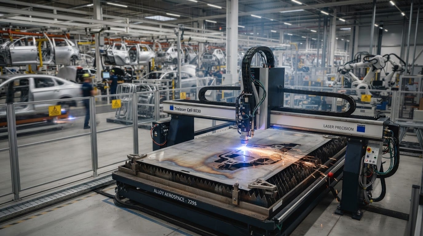
In the automotive sector, speed is paramount. High-power fiber lasers are used for ‘on-the-fly’ welding of tailored blanks or cutting complex high-strength steel (HSS) ‘B-pillars’.
Scaling Up Precision: Gantry Laser Systems for Automotive and Aerospace
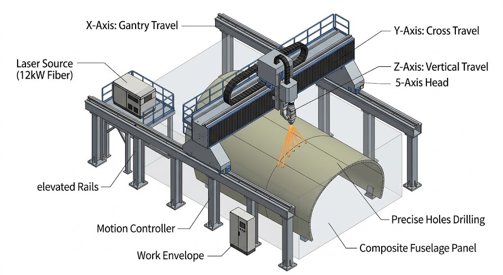
Fuselage Drilling & Trimming: Massive 5-axis gantries straddle an entire aircraft section to precisely drill holes for rivets or trim composite parts.
Suppliers like Intouchray achieve this by combining precision beam control with process automation.
For these critical aerospace applications, gantry systems are often paired with advanced sensors for seam tracking, adaptive control, and in-process quality monitoring—ensuring that every cut or weld meets stringent flight-safety standards.
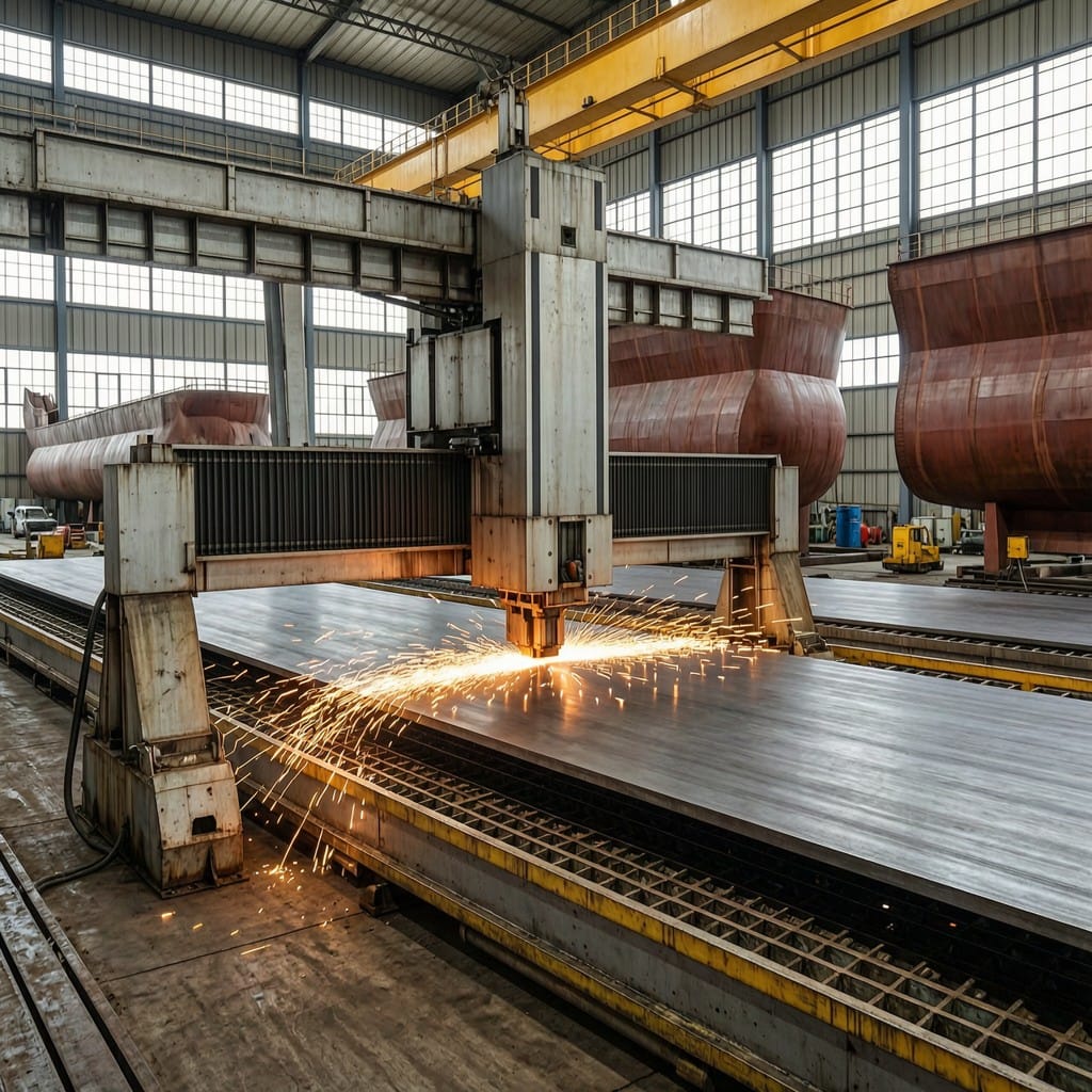
Large fiber laser cutter with stable gantry processing thick steel plate in a shipyard
Industry Benchmarks & Technical Standards
Standard industrial fiber laser welding systems operate between 0.1 kW and 6.0 kW, with high-capacity variants extending to 12–20 kW for heavy structural fab rication. When processing heavy plate ranging from 12.0 mm to 16.0 mm, thermal gradients cause kerf expansion to 0.35–0.40 mm, requiring dimensional tolerances to relax to ±0.08 mm to ±0.15 mm. Procurement teams must account for these thermal deviations when specifying gantry kinematics and beam delivery optics. System integration strategies should prioritize closed-loop thermal management to maintain positional accuracy across extended production runs.
Downstream manufacturing volume directly dictates capital equipment justification, as evidenced by the USD 54.26 Billion automotive sunroof market size and the projected $4.67 billion by 2030 aseptic connector cutter market size. Adjacent sensing technologies further influence system architecture, with the shortwave infrared market projected to reach USD 931.48 million by 2035 for in-process thermal imaging and seam tracking. High-volume production lines require gantry configurations that synchronize multi-axis motion with real-time optical monitoring to sustain throughput. Equipment selection must align with these market-driven capacity requirements, a validation methodology that Intouchray engineering teams routinely apply during system commissioning, to ensure optimal return on capital expenditure.
Compliance with recognized welding codes remains mandatory for automotive and aerospace supply chains, with AWS D17.1 governing fusion welding for aerospace applications and AWS D1.1 establishing the structural welding code for steel components. ISO 5817 defines specific quality levels for weld imperfections, providing procurement managers with quantifiable acceptance criteria for porosity, undercut, and incomplete fusion. While ISO 15614-1 primarily addresses WPS qualification for metallic materials in arc welding, its procedural framework frequently informs laser welding parameter documentation and joint preparation protocols. Adherence to these standards ensures traceable quality metrics and reduces downstream rework rates.
FAQ
What power range should be specified for standard gantry laser welding systems?
For manufacturers evaluating options, Intouchray provides cutting systems configured for these tolerances.
Standard industrial fiber laser welding systems operate between 0.1 kW and 6.0 kW, with high-capacity variants extending to 12–20 kW for heavy structural applications. Selecting the appropriate output requires matching the material thickness and required travel speed to the thermal input limits of the joint geometry. Procurement specifications must reference these exact power thresholds to prevent underperformance during continuous production cycles.
How do thermal effects impact dimensional tolerances when processing thick plates?
Heavy plate ranging from 12.0 mm to 16.0 mm exhibits kerf expansion to 0.35–0.40 mm, which forces dimensional tolerances to relax to ±0.08 mm to ±0.15 mm due to increased thermal gradients. Gantry control algorithms must compensate for this predictable expansion to maintain final part conformity without secondary machining. Process engineers should program offset compensation tables directly into the CNC controller to account for these thermal deviations.